
Beamforming is considered an essential part of mmWave (millimeter wave) 5G
5G mmWave offers huge potential capacity by virtue of providing large numbers of transmitting and receiving antennas as well as enormous channel bandwidth, and beamforming is an essential technology to make the 5G mmWave useful to users.
The limit of large number of antennas (theoretically going to infinite numbers) , small scale fading effects vanish by virtue of channel hardening and channel vectors from the BS to the users tend to become orthogonal. As a result plain channel matched beamforming at base station permits serving several users at the same time–frequency resource slot with no interference.
The Massive MIMO challenge
One problem with massive MIMO systems is the cost and complexity of hardware to efficiently exploit large number of antennas in mm wave region. Based on current vendor mmWave products, the number of antenna elements at the gNB can vary from 128 to more than 1,000
Also with mmWave, support for beam-sweeping is critical to estimate / identify the direction of interest. This procedure increases the overhead from CSI acquisition, which grows with the number of antennas since the beams become narrower and hence arising the need to support more beams.
Beamforming gain at mmWave is high compared to sub-6GHz since more number of antenna elements can be packed in the same form factor, resulting in a sharper beam. Also, this sharper beam can improve spatial separation between users and hence increase MU-MIMO performance.
Beamforming Technology
hybrid beamforming is achieved by a set of antenna arrays. Each antenna array
consists of several antenna elements and each antenna array can be mapped with one RF Chain.
The center lobe gain of each beam is determined by the overall gain achieved by combining the gains from all the antenna elements of the array. The number of phase shifters and number of antenna elements will further determine the number of beam directions that can be generated.
In adaptive beamforming, system can automatically learn based on performance metrics and close loop management, the required beambook to provide optimal coverage in any given cell.

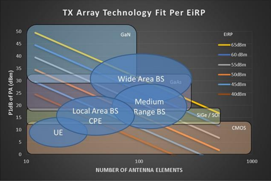
Given the high variation in deployment scenarios, whether the area is highly treed, or composed of street canyons, or wide-open spaces, there will be a large range of path loss to contend with on a case by case basis. For example, in a dense urban deployment where LOS is assumed, the EIRP target may be as low as 50 dBm
Phased Arrays and Holographic Beamformers
At mmWave frequencies, only Phased Arrays and Holographic Beamformers are viable candidates. Massive MIMO is not mature enough for mmWave deployment. One common design point for gNBs is that of a 60dBm transmit EIRP (@P1dB), single polarization beamformer suitable for mmWave operation.
Phased arrays targeted for this application are frequently 256 element transmit arrays (either 16 row and 16 column or 8 row and 32 column). The antenna array has 28dB of realized gain (29dB for a ‘perfect’ antenna array). Quad-element phased array chipsets becoming common in a variety of technology nodes.
64 of these driver chips would be needed to drive the 256 element array. Phased arrays distribute electronic gain to each element, resulting in a small transmit power requirement of 6.2mW per element for a total transmitted power of 32dBm. The combination of 32dBm electronic gain and 28dB antenna gain meets the 60dBm EIRP target. For Silicon based chips the expected Power Added Efficiency (PAE) is roughly 4% which means such an array will need at least 40W of DC input power. More efficient technology nodes exist (SiGe, GaAs, and GaN) but the cost generally scales with performance
An HBF of equal aperture size to the phased array would have 640 total elements driven by a single high power amplifier (rather than distributed into the array). An HBF of this size would have 26dB of antenna gain and thus need a GaN power amplifier able to source 34dBm (2.5W). GaN is generally higher performance, with off the shelf power amps reaching 25% PAE. This single amplifier approach has the added benefit of being able to exploit digital predistortion techniques to linearize the PA which is normally impossible for phased arrays. HBF also has a small control overhead driven by the number of control ASICs needed for switching the element states. For an array of this size the control overhead is roughly 2.9W.
This quantity is also present in Phased Arrays but is captured within the PAE of the chipset
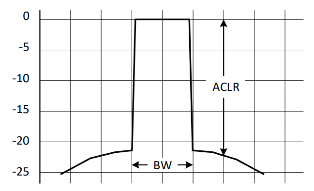
A typical spectrum of a modulated 5G NR signal is illustrated in Figure 8-27, which consists of many OFDM modulated sub-carriers. Since the transmitter is not ideal, intermodulation between the sub-carriers will occur when the modulated signal is amplified, up-converted and phase-shifted. All odd-number of intermodulation (IM3, IM5, IM7 and so on) will result in intermodulation products falling in-band as well as in the adjacent channels. The power from these intermodulation products that ends up in the adjacent channel is referred to in the 5G NR standard as the Adjacent Channel Leakage power Ratio (ACLR) and is defined as the ratio of the filtered mean power centered on the assigned channel frequency to the filtered mean power centered on an adjacent channel frequency. The ACLR requirement is specified for a scenario in which the adjacent carrier is another NR channel and should be > 17 dB for a mm-wave 5G NR signal.
This requirement can only be fulfilled by a sufficiently linear transmitter, since RF channel filtering is not practical at mm-wave frequencies.
mmWave Antennas
Due to the very short wavelength at mmWave frequencies, a single half-wave dipole antenna would be only 4-5mm long. To achieve increased range, a small group of antenna elements (usually 4 or 8) are arranged in an array and phased to concentrate the transmitted power in a relatively narrow beam.
Relative to transmitting the same total power from one antenna, the array achieves added gain of 10logN where N is the number of elements in the array. This gain applies in both transmit and receive. Antenna array factors that degrade the array performance from this ideal include direct coupling between the elements, surface waves with edge reflections, and differences in element patterns due to the finite overall structure size.
Dual/circular polarization antennas
The use of multiple operating arrays provide a mechanism for MIMO operation. In this case, the arrays beamform as needed in different directions into the multipath environment, to create multiple spatial channels, thus widening the total data pipe with proper decoding. If the individual antenna element is of a type that can be driven in orthogonal polarizations (as is the case for a patch antenna), the order of diversity or MIMO for the system can be further extended by driving these polarizations independently.
Reconfigurable antennas/arrays to realize large beam-scan coverage
Reconfigurability can be applied to several aspects of UE mmWave antennas.
- Radiation pattern modifications for individual antenna elements
- Switching between directional sub-elements
- Polarization modifications.
- Using 1 and/or 2 in an array to increase scan angle and reduce the arrays required for spherical coverage.
Low-loss beam-steering antenna arrays without phase shifters
The insertion losses of commercially available semiconductor-based phase shifters at mmWave frequencies are too high for passive beam forming in UE arrays thus the arrays require active beam steering circuits. Also, the performance of phased arrays are also limited by the variation in delay with frequency of the phase shifters, leading to shifts in beam pointing over a wide bandwidth. Moreover, the array element distance, which depends on the selected frequency, influences the gain at the lowest frequency and the coverage at the highest frequency of the interval. Smartphone mmWave antennas do not require very high directivity, only what is sufficient to provide the specified peak EiRP and wide spatial coverage, their element power beam-widths typically can stay in the range of 60°-90°. This means the number of beam states can be kept small, e.g. to 4-5 states per panel. While phased arrays can offer much higher resolutions, this is unnecessary for UE applications. In turn this implies beams can be controlled by simple switching schemes instead of phase shifters. Available switches offer <2 dB I.L. throughout 24-40 GHz compare to 4-7 dB phase shifter losses. Additionally, the beam direction of each setting does not depend on the alignment of multiple chains of electronics with and more consistent performance over environmental variation and over the terminal lifetime should be realized. This may also reduce test and calibration time. The antenna configurations utilizing switching schemes can take any of the following forms: Single directive element (e.g. Yagi) antennas distributed around the UE chassis pointing in different directions Couplers and delay-lines with switches configured in a Butler Matrix formation for small array Various ESPAR arrays configured by switches or tuners
High performance beam steering / beamforming components
The choice of architecture for beam forming in terminals depends strongly on the performance of the circuit elements available and their effective integration. For example, if small, high-performance switches were available, architectures with switches between the antenna elements and the active circuits would become feasible. Similarly, if integrated low-loss phase shifters were available (1dB or less), passive beam forming would become attractive, leading to reduced interference and easier calibration. Additionally, the
need for beam-steering systems that preserve their performance over multiple FR2 bands may drive a need for mmWave tuning for matching the antenna elements and for side-lobe suppression. The multiband requirement also will likely drive the need for tuning and/or reconfigurability throughout the signal chain.
Technologies for mmWave Base Station radios with Beamforming
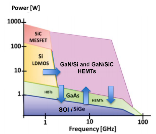
The gain of the phased array is proportional to the number of array elements (N). On the Receiver (Rx)side, the array gain improves receive sensitivity (SNR) by a factor of N, whereas on the Transmitter(Tx) side, the combination of array gain and additional power per element results in an N2 increase in output power as compared to a single element. This fundamental property of the phased array enables a tradeoff between semiconductor performance and the size of array needed to meet system requirements. In particular, the N2 reduction in output power per element to achieve the same system EIRP targets makes
silicon technologies an attractive choice for all but the highest power applications.
Base stations and handsets have different output power specifications and specifications are also quite different depending on chosen architecture (phase array complexity and system integration approach).
Nowadays, all silicon and compound semiconductor technologies are competing for 5G mmWave base stations as well as handset.
Typical gNodeB mmWave 5G implementations
Several RAN vendors have well defined products and roadmap features to support mmWave bands. Products typically support BW up to 800MHz and EIRP ranging between 55-60dBm.
Maximum Output Power for 5G mmWave
In term of maximum transmission power of UE in mmWave, FCC has set the max radiated total EIRP limit for mobile station as 43 dBm, including mobile handset, for mmWave bands from 28 GHz to 39 GHz.
Also, FCC sets the max EIRP limit for transportable station (transmitting equipment that is not intended to be used while in motion, but rather at stationary locations) as 55 dBm.
Conclusions for 5G mmWave and Beamforming
While mmWave frequencies have been used in the past for satellite or point-to-point and point-to-multipoint backhaul connections, this is the first time that those frequencies have become part of 3GPP global standards for the intended use of terrestrial mobile along fixed access networks. Such progression has been made possible through various technological advancements, including massive MIMO coupled with beamforming technologies, advancement in chipset processing power, and the overall RF front-end/antenna subsystem integration/innovation for base station equipment as well as user equipment.
The limited propagation characteristics of mmWave spectrum due to their high frequency range, poor outdoor-to-indoor penetration due to building materials attenuation, as well as other environmental and weather factors have been well understood in the past. However, advancements in Massive-MIMO systems coupled with beamforming technologies related to fast beam-tracking, assignment, and switching intend to compensate for some of these shortcomings when mmWave spectrum is deployed in mobile networks
For Further Information
Please Contact Us